I have below instructions on how to get a cheap raspberry pi serial cable to run on an arduino pro mini 5v.
The background
I recently got in to arduinos. I fought it hard (I didn’t need to learn yet another technology I’ll never really be able to use in real life), but I finally broke down and got one because I wanted to do some EEPROM mods. Arduinos can just make some of these tasks easier. Turns out, they are really awesome for all the circuits I was doing by hand.
Go figure.
Anyway, I showed my wife the IDE and a few basics like turning on LEDs and light/voltage sensing and she was really interested. It was easy and she thought that maybe she could use some for work. Since I’m using arduino mini’s, I now had need for a serial cable out of her laptop so she can tinker at the same time as I do. I don’t want to drop another $18 for an FTDI breakout board (cheaper ones apparently don’t always work with windows as of late). So we looked around, but I wound up deciding that I wanted to try one of the console cables that came with my raspberry pi kit. Worst case, I would just learn a bit and breakdown and buy a better one. Turns out they work just fine, despite the disclaimers at the bottom of every page saying that they don’t work with arduinos.
Procedure
I used the instructable here as a guide, but made a few basic mods that made it easier for my wife to follow.
Materials
- An arduino pro mini (or knockoff)
- Raspberry pi console cable
** Mine actually came with a raspberry pi kit, so it may not be this exact link. I would be interested if maybe the new Windows 8 Model is just as easy. - Optionally, Jumper Wires
- Moderate Soldering skills
Disclaimer
It should go without saying, but there is no warranty of any sort on anything here. This is my experience, and it may not be the same for you. In fact, it could do a number of terrible things such as burn out your arduino/cable/computer. For all I know it may catch something on fire or you may sustain terrible shocks or burns. If you follow my lead, you are taking responsibility for all of your actions yourself, not me. Use your own head and decide if it’s safe to repeat these steps and deal with any consequences yourself. In fact, I suggest you don’t do any of this and only read it for your own information. As far as we’re all concerned it’s realistic fiction… Do not try this. Ever.
Overview
Basically, the reason these are so cheap is that they use a different serial chip, which is not FTDI branded. The nice part about that is that you don’t need to worry about getting a genuine chip or being forced into linux. I have used this cable in the past multiple times from OS X for raspberry pi and windows 7, so I expect this is just as cross platform as the FTDI variants.
These cables run at 3.3v for communication, but provide a 5v pin for power. It turns out that the 5v variant actually does not have any issue here. I do not know the nitty gritty, but I expect that means that the 3v variant of the arduino might be able to use this too with some small mods.
This cable definately works out of the box just fine, if you’re willing to press reset manually just before the upload happens (but after the compile) in the arduino IDE. That is fine with me, but it’s easier if there is a reset button, so this procedure will actually bring that pin out to your arduino to make it happen.
Procedure
- Break open the USB connector, and solder a new wire to DTS.
- This is easy, I just had to pull apart two pieces of plastic that were held together with friction and a wish.
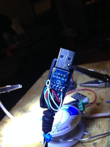
- Inside, all of the standard pins were available and labeled on the back, just soldered right to the one I needed.
- I filed out a small notch for my new wire to go through and made a little loop in the wire so that if the wire is pulled, it stops at the notch rather than pull on the PCB.
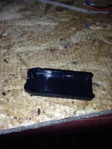
- Closed it all back up
- This is easy, I just had to pull apart two pieces of plastic that were held together with friction and a wish.
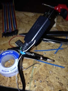
- Prepare the ribbon
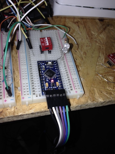
- The ribbon I used is optional. There are lots of ways to hook up to the arduino. The reason I wound up using the ribbon was that it made things very easy to make sense out of. The arduino pro mini has blk and grn written on the corners of the board to explain how to put such a ribbon. Wouldn’t you know it, the ribbon I had laying around started and ended with black and green over 6 pins. Too coincidental, and it makes the order easy, rather than remembering a complicated mapping.
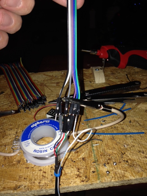
- Wire up the arduino. Below is a quick outline of how the mapping goes:
- From the BLK to the GRN, the mapping goes:
- (Empty, GND, VCC, RX, TX, DTS)
- In the case of my cable, that works out to… (Empty, Black, Red, Green, White, new DTS Wire)

- Profit.
- All done, just plug in and use it. It’s worth noting that the thing still requires the drivers as outlined in the RPi instructions or with the cable or wherever.

- After it’s all installed (and plugged in and working). Just need to choose the COM port for the new adaptor in the IDE and make sure the right board is selected from the tools -> board menu (in my case it’s “arduino pro or pro mini (5V,16 Mhz) w/ ATMEGA328”) and pow. Done.
- All done, just plug in and use it. It’s worth noting that the thing still requires the drivers as outlined in the RPi instructions or with the cable or wherever.


Lessons Learned
- The DTR pin on the arduino header is NOT the reset pin. Wiring up the arduino on the breadboard and assuming that the reset pin is the same as the pin that comes off the communication header is a total fail. You will waste a lot of time.
- If the reset pin on the breadboard MUST be used, solder to the RTS pin and put a 1microfarad capacitor between it and the reset pin, as the instructions say… except in our case it’s RTS, not DTR.
You must log in to post a comment.